Wi-Fi (Wireless LAN)
Infix supports Wi-Fi as a client (Station), as an Access Point, as an 802.11s mesh point, and as a 4-address (WDS) link for wireless bridges and repeaters. When a compatible Wi-Fi adapter is detected, the system automatically creates a WiFi radio (PHY) in factory-config, that can host virtual interfaces.
Architecture Overview
Infix uses a two-layer WiFi architecture:
-
WiFi Radio (PHY layer): Represents the physical wireless hardware
- Configured via
ietf-hardwaremodule - Controls channel, transmit power, regulatory domain
- One radio can host multiple virtual interfaces
- Configured via
-
WiFi Interface (Network layer): Virtual interface on a radio
- Configured via
infix-interfacesmodule - Operates in Station (client), Access Point, Mesh Point or WDS link mode
- Each interface references a parent radio
- Configured via
Naming Conventions
Like other interface types in Infix, WiFi components follow naming conventions that allow the CLI to automatically infer types:
| Name Pattern | Type | Description |
|---|---|---|
radioN |
WiFi Radio | Hardware component for WiFi PHY |
wifiN |
WiFi Interface | Virtual WiFi interface on a radio |
Where N is a number (0, 1, 2, ...).
Tip
Using these naming conventions simplifies configuration since type/class
settings are automatically inferred. For example, creating a hardware
component named radio0 automatically sets its class to wifi, enabling
the wifi-radio configuration container.
Note: This inference only works with the CLI. Configuring WiFi over NETCONF or RESTCONF requires setting the class/type explicitly.
Current Limitations
- USB hotplug is not supported - adapters must be present at boot
- Interface naming may be inconsistent with multiple USB Wi-Fi adapters
- A station and access points on the same radio must share a channel: the station follows its access point, so pin the radio to that channel on both ends. See WDS Backhaul and Repeaters
Supported Wi-Fi Adapters
Wi-Fi support is primarily tested with Realtek chipset-based adapters.
Known Working Chipsets
- Built-in Wi-Fi on Banana Pi BPi-R3
- Built-in Wi-Fi on Raspberry Pi 4/CM4
- Realtek:
- RTL8188CU
- RTL8188FU
- RTL8821CU
Other Realtek chipsets may work but are not tested.
Note
Some Realtek chipsets require proprietary drivers not included in the standard kernel.
- Firmware requirements vary by chipset
- Check kernel logs if your adapter is not detected
USB WiFi Dongles
USB WiFi dongles may be slow to initialize at boot due to firmware
loading. If your USB dongle is not detected reliably, configure a
probe-timeout on the radio to wait for the PHY:
admin@example:/> configure
admin@example:/config/> edit hardware component radio0 wifi-radio
admin@example:/config/hardware/component/radio0/wifi-radio/> set probe-timeout 30
admin@example:/config/hardware/component/radio0/wifi-radio/> leave
This waits up to 30 seconds for the radio PHY to appear before creating WiFi interfaces. If the PHY is not detected within the timeout, a dummy interface is created as a placeholder, allowing IP configuration to proceed. Reboot when the radio becomes available.
Radio Configuration
Before configuring WiFi interfaces, you must first configure the WiFi radio.
Radios are automatically discovered and named radio0, radio1, etc.
Country Code ⚠
The country code is one setting for all radios in the system, since the regulatory domain is one setting in the kernel. It defaults to "00", the world domain: no 6 GHz, listen-only on 5 GHz, and no access point or mesh point can be configured. Some systems ship with a factory default (typically "DE" for the BPi-R3).
admin@example:/> configure
admin@example:/config/> set hardware wifi country-code DE
admin@example:/config/> leave
Legal notice!
The country code is legally required and determines which WiFi channels and power levels are permitted in your location. Using an incorrect country code may violate local wireless regulations.
Common country codes, see ISO 3166-1 alpha-2 for the complete list:
- Europe:
- DE: Germany
- SE: Sweden
- GB: UK
- FR: France
- ES: Spain
- Americas:
- US: United States
- CA: Canada
- BR: Brazil
- Asia-Pacific:
- JP: Japan
- AU: Australia
- CN: China
Basic Radio Setup
Configure the radio with band and channel. The country code above covers all radios.
For Station (client) mode:
admin@example:/> configure
admin@example:/config/> edit hardware component radio0 wifi-radio
admin@example:/config/hardware/component/radio0/wifi-radio/> leave
For Access Point mode:
admin@example:/> configure
admin@example:/config/> edit hardware component radio0 wifi-radio
admin@example:/config/hardware/component/radio0/wifi-radio/> set band 5GHz
admin@example:/config/hardware/component/radio0/wifi-radio/> set channel 36
admin@example:/config/hardware/component/radio0/wifi-radio/> set channel-width 80MHz
admin@example:/config/hardware/component/radio0/wifi-radio/> leave
Key radio parameters:
⚠ Must match your physical location for legal compliance! ⚠
- band: 2.4GHz, 5GHz, or 6GHz (required for AP mode). Automatically enables
appropriate WiFi standards:
- 2.4GHz: 802.11n/ax
- 5GHz: 802.11n/ac/ax
- 6GHz: 802.11ax
- channel: Channel number (1-233) or "auto". When set to "auto", defaults to
channel 6 for 2.4GHz, channel 36 for 5GHz, or channel 37 for 6GHz
- channel-width: AP channel bandwidth. Supported values are auto, 20MHz,
40MHz, 80MHz, and 160MHz. Wider channels require matching hardware,
regulatory approval, and are only available on 5GHz/6GHz where supported.
- legacy-rates: Allow legacy 802.11b rates (1, 2, 5.5, 11 Mbps) on 2.4GHz
(default: disabled). Slow 802.11b clients consume excessive airtime and
degrade throughput for all stations, so the rates are normally suppressed.
Enable only when old 2.4GHz-only IoT devices need them to associate. No
effect on 5GHz/6GHz.
- probe-timeout: Seconds to wait for PHY detection at boot (default: 0). Set
to a non-zero value (e.g., 30) for USB WiFi dongles that are slow to
initialize due to firmware loading
Note
TX power is still determined by the driver based on regulatory
constraints and hardware capabilities. Channel width can now be set
explicitly for AP mode, or left at auto to let the driver choose.
Bands and Channels
Each band strikes a different balance between range and capacity. The
country-code decides which channels are legal in your location; the
lists below are the common allocations, and your regulatory domain may
allow fewer.
2.4 GHz
Channels 1-13 are available in most of the world, 1-11 in the US and Canada, and 14 in Japan (802.11b only). At 20 MHz only three channels avoid overlap: 1, 6, and 11. A 40 MHz channel takes up most of the band, so it is seldom worth using here.
Drawbacks:
- This is the most crowded band. It is shared with Bluetooth, Zigbee, cordless phones, microwave ovens, and most of the neighboring Wi-Fi.
- Narrow channels and constant contention hold real throughput well below 5 and 6 GHz.
- The upside is range: 2.4 GHz reaches further and passes through walls better, which keeps it useful for distant clients and 2.4 GHz-only IoT devices.
5 GHz
UNII-1 (channels 36-48) and UNII-3 (149-165) need no radar checks. UNII-2 (channels 52-64 and 100-144) shares spectrum with radar and requires DFS. ETSI regions such as the EU do not include UNII-3, so the only non-DFS 5 GHz channels there are 36-48. This band supports 20, 40, 80, and 160 MHz, so it is the one to use for wide, fast channels.
Drawbacks:
- Shorter range than 2.4 GHz, and a weaker signal through walls and floors.
- A DFS channel must be monitored for radar for 60 seconds (up to 10 minutes near some weather radars) before the AP may transmit, which delays start-up. If radar appears later, the AP has to leave the channel within 10 seconds and avoid it for 30 minutes, dropping clients during the move.
- The widest 80 and 160 MHz channels almost always sit on DFS spectrum, so the same radar rules apply to them.
6 GHz
The FCC regions open 59 channels (1, 5, 9 ... 233) across 5925-7125 MHz.
ETSI regions, including the EU, currently open only the lower part,
5945-6425 MHz (channels 1-93), for indoor use. Clients find networks on
the 15 Preferred Scanning Channels (5, 21, 37 ... 229) spaced every
80 MHz, and auto selects channel 37. There is no DFS in 6 GHz, so
there is no radar start-up delay.
Drawbacks:
- The shortest range and the weakest wall penetration of the three bands.
- Only Wi-Fi 6E and newer clients can use it; older phones and IoT devices cannot see the band at all.
- AP operation requires WPA3-Personal (SAE) with management frame protection, so WPA2-only and open networks are rejected.
- Indoor power limits cap coverage further.
WiFi 6 Support
WiFi 6 (802.11ax) is always enabled in AP mode on all bands, providing improved performance through features like OFDMA, BSS Coloring, and beamforming.
WiFi 6 Features (always enabled in AP mode on supported radios):
- OFDMA: Better multi-user efficiency in dense environments
- BSS Coloring: Reduced interference from neighboring networks
- Beamforming: Improved signal quality and range
Requirements:
- Hardware must support 802.11ax
- Client devices must support WiFi 6 for full benefits
- Older WiFi 5/4 clients can still connect but won't use WiFi 6 features
Important
6 GHz AP operation requires WPA3-Personal (SAE) with mandatory management frame protection. Open networks and WPA2-only AP configurations are not valid on 6 GHz.
Discovering Available Networks
Before connecting to a WiFi network, you need to discover which networks are available. Infix automatically scans for networks when a WiFi interface is created with a radio reference.
Enable Background Scanning
To enable scanning without connecting, configure the radio and create a WiFi interface referencing it:
Step 1: Configure the radio
admin@example:/> configure
admin@example:/config/> edit hardware component radio0 wifi-radio
admin@example:/config/hardware/component/radio0/wifi-radio/> leave
Step 2: Create WiFi interface with radio reference only
admin@example:/> configure
admin@example:/config/> edit interface wifi0
admin@example:/config/interface/wifi0/> set wifi radio radio0
admin@example:/config/interface/wifi0/> leave
The system will now start scanning in the background. The interface will operate in scan-only mode until you configure a specific mode (station or access-point).
View Available Networks
Use show interface to see discovered networks and their signal strength:
admin@example:/> show interface wifi0
name               : wifi0
type               : wifi
index              : 3
mtu                : 1500
operational status : up
ip forwarding      : enabled
physical address   : f0:09:0d:36:5f:86
ipv4 addresses     : 192.168.1.100/24 (dhcp)
ipv6 addresses     :
in-octets          : 148388
out-octets         : 24555
mode               : station
ssid               : MyNetwork
bssid              : b4:fb:e4:17:b6:a7
signal             : -45 dBm (good)
rx bitrate         : 72.2 Mbps
tx bitrate         : 86.6 Mbps
──────────────────────────────────────────────────────────────────────
Available Networks
SSID                 BSSID              SECURITY       SIGNAL  CHANNEL
MyNetwork            b4:fb:e4:17:b6:a7  WPA2-Personal  good          6
GuestWiFi            c8:3a:35:12:34:56  WPA2-Personal  fair         11
CoffeeShop           00:1a:2b:3c:4d:5e  Open           bad           1
In the CLI, signal strength is reported as: excellent, good, fair or bad.
For precise signal strength values in dBm, use NETCONF or RESTCONF to access
the signal-strength leaf in the operational datastore.
When connected, bssid shows the MAC address of the access point the
station is associated to. It appears only while connected. When several
access points share one SSID (a roaming network), the bssid is what
tells them apart, and it changes as the station roams between them.
Channel Survey
A channel survey shows how busy each channel is, which helps when picking a channel for an access point or when a link performs worse than its signal strength suggests. The radio has to leave its operating channel to measure the others, so traffic on it pauses for a few seconds. Because of that the survey only runs when asked for, it is not collected in the background.
admin@example:/> show hardware radio0 survey
The output lists every channel the radio supports with its noise floor and
utilization, marks the operating channel, and suggests the least busy
channels per band. A radio that has no interface yet can be surveyed too,
which helps when picking a band and channel for it. Add passive to listen longer on each channel without sending
probe requests, which gives a steadier utilization reading at the cost of a
longer pause.
In the WebUI, each radio on the WiFi page has a Scan channels button that draws the same survey as a chart.
Over NETCONF or RESTCONF the survey is the channel-survey action on the
radio's hardware component. Its output is a list of channels keyed by
frequency, with the busy, receive and transmit time out of the total time
the radio spent listening on each.
Passphrase Requirements
To ensure your connection is secure and compatible with all network hardware, your passphrase must meet the following criteria:
- Length: Between 8 and 63 characters
- Characters: Use only standard English keyboard characters
- Allowed: Letters (A-Z, a-z), numbers (0-9), and common symbols (e.g., ! @ # $ % ^ & * ( ) _ + - = [ ] { } | ; : ' " , . < > / ? ~)
- Spaces: Spaces are allowed, but not at the very beginning or very end of the passphrase
- Prohibited: Emojis, accented characters (like á or ñ), and special "control" characters
Why the limit?
Standard WiFi security (WPA2/WPA3) requires a minimum of 8 characters to
prevent "brute-force" hacking. The character limit ensures your password
works on older routers and various operating systems.
Tips for password strength, see XKCD #936.
Station Mode (Client)
Station mode connects to an existing Wi-Fi network. Before configuring station mode, follow the "Discovering Available Networks (Scanning)" section above to scan for available networks and identify the SSID you want to connect to.
Step 1: Configure Password
Create a keystore entry for your WiFi password (8-63 characters):
admin@example:/> configure
admin@example:/config/> edit keystore symmetric-key my-wifi-key
admin@example:/config/keystore/…/my-wifi-key/> set key-format passphrase-key-format
admin@example:/config/keystore/…/my-wifi-key/> edit cleartext-symmetric-key
Passphrase: ************
Retype passphrase: ************
admin@example:/config/keystore/…/my-wifi-key/> leave
The edit command prompts for the passphrase interactively and
handles the base64 encoding required by the keystore automatically.
Step 2: Connect to Network
Configure station mode with the SSID and password to connect:
admin@example:/> configure
admin@example:/config/> edit interface wifi0
admin@example:/config/interface/wifi0/> set wifi station ssid MyHomeNetwork
admin@example:/config/interface/wifi0/> set wifi station security secret my-wifi-key
admin@example:/config/interface/wifi0/> leave
The connection attempt will start immediately. You can verify the connection status:
admin@example:/> show interface wifi0
name               : wifi0
type               : wifi
operational status : up
physical address   : f0:09:0d:36:5f:86
mode               : station
ssid               : MyHomeNetwork
bssid              : b4:fb:e4:17:b6:a7
signal             : -52 dBm (good)
Station configuration parameters:
radio: Reference to the WiFi radio (mandatory) - already set during scanningstation ssid: Network name to connect to (mandatory)station security mode:auto: default, WPA2/WPA3 auto-negotiationdisabled: open network
station security secret: Reference to keystore entry, required unless mode isdisabled
Note
The auto security mode automatically selects WPA3-SAE or WPA2-PSK based on
what the access point supports, prioritizing WPA3 for better security.
Certificate-based authentication (802.1X/EAP) is not yet supported.
Access Point Mode
Access Point (AP) mode allows your device to create a WiFi network that other devices can connect to. APs are configured as virtual interfaces on a WiFi radio.
Basic AP Configuration
First, ensure the radio is configured (see Radio Configuration above). Then create a keystore entry for your WiFi password and configure the AP interface:
Step 1: Create keystore entry for the WiFi password
admin@example:/> configure
admin@example:/config/> edit keystore symmetric-key my-wifi-secret
admin@example:/config/keystore/…/my-wifi-secret/> set key-format passphrase-key-format
admin@example:/config/keystore/…/my-wifi-secret/> change cleartext-symmetric-key
Passphrase: ************
Retype passphrase: ************
admin@example:/config/keystore/…/my-wifi-secret/> end
Step 2: Create the AP interface
admin@example:/config/> edit interface wifi0
admin@example:/config/interface/wifi0/> set wifi radio radio0
admin@example:/config/interface/wifi0/> set wifi access-point ssid MyNetwork
admin@example:/config/interface/wifi0/> set wifi access-point security secret my-wifi-secret
admin@example:/config/interface/wifi0/> leave
Note
Using wifiN as the interface name automatically sets the type to WiFi.
Alternatively, you can use any name and explicitly set type wifi.
Access Point configuration parameters:
radio: Reference to the WiFi radio (mandatory)access-point ssid: Network name (SSID) to broadcastaccess-point hidden: Set totrueto hide SSID (optional, default: false)access-point security mode: Security mode (see below)access-point security secret: Reference to keystore entry (for secured networks)
Security modes:
open: No encryption (not recommended)auto: WPA2/WPA3 transitional mode on 2.4/5 GHz, WPA3-only on 6 GHzwpa2-personal: WPA2-PSK (most compatible)wpa3-personal: WPA3-SAE (more secure, requires WPA3-capable clients)wpa2-wpa3-personal: Mixed mode (maximum compatibility)
SSID Hiding
To create a hidden network that doesn't broadcast its SSID:
admin@example:/config/interface/wifi0/> set wifi access-point hidden true
Multi-SSID Configuration
Multiple AP interfaces on the same radio allow broadcasting multiple SSIDs, each with independent security settings. This is useful for guest networks, IoT devices, or segregating traffic into different VLANs.
Step 1: Configure the radio (shared by all APs)
admin@example:/> configure
admin@example:/config/> set hardware wifi country-code DE
admin@example:/config/> edit hardware component radio0 wifi-radio
admin@example:/config/hardware/component/radio0/wifi-radio/> set band 5GHz
admin@example:/config/hardware/component/radio0/wifi-radio/> set channel 36
admin@example:/config/hardware/component/radio0/wifi-radio/> leave
Step 2: Configure keystore secrets
admin@example:/> configure
admin@example:/config/> edit keystore symmetric-key main-secret
admin@example:/config/keystore/…/main-secret/> set key-format passphrase-key-format
admin@example:/config/keystore/…/main-secret/> change cleartext-symmetric-key
Passphrase: ************
Retype passphrase: ************
admin@example:/config/> edit keystore symmetric-key guest-secret
admin@example:/config/keystore/…/guest-secret/> set key-format passphrase-key-format
admin@example:/config/keystore/…/guest-secret/> change cleartext-symmetric-key
Passphrase: ************
Retype passphrase: ************
admin@example:/config/> edit keystore symmetric-key iot-secret
admin@example:/config/keystore/…/iot-secret/> set key-format passphrase-key-format
admin@example:/config/keystore/…/iot-secret/> change cleartext-symmetric-key
Passphrase: ************
Retype passphrase: ************
admin@example:/config/keystore/…/iot-secret/> leave
Step 3: Create multiple AP interfaces (all on radio0)
admin@example:/> configure
# Primary AP - Main network (WPA3 for maximum security)
admin@example:/config/> edit interface wifi0
admin@example:/config/interface/wifi0/> set wifi radio radio0
admin@example:/config/interface/wifi0/> set wifi access-point ssid MainNetwork
admin@example:/config/interface/wifi0/> set wifi access-point security mode wpa3-personal
admin@example:/config/interface/wifi0/> set wifi access-point security secret main-secret

# Guest AP - Guest network (WPA2/WPA3 mixed for compatibility)
admin@example:/config/> edit interface wifi1
admin@example:/config/interface/wifi1/> set wifi radio radio0
admin@example:/config/interface/wifi1/> set wifi access-point ssid GuestNetwork
admin@example:/config/interface/wifi1/> set wifi access-point security mode wpa2-wpa3-personal
admin@example:/config/interface/wifi1/> set wifi access-point security secret guest-secret

# IoT AP - IoT devices (WPA2 for older device compatibility)
admin@example:/config/> edit interface wifi2
admin@example:/config/interface/wifi2/> set wifi radio radio0
admin@example:/config/interface/wifi2/> set wifi access-point ssid IoT-Devices
admin@example:/config/interface/wifi2/> set wifi access-point security mode wpa2-personal
admin@example:/config/interface/wifi2/> set wifi access-point security secret iot-secret
admin@example:/config/interface/wifi2/> leave
Note
Each WiFi interface gets its own MAC address, derived from the chassis
MAC by changing only the first octet: the locally administered bit is
set and the interface number plus one is stored in the upper bits. On
a device with chassis MAC 00:53:00:c0:ff:ee, wifi0 becomes
06:53:00:c0:ff:ee and wifi1 becomes 0a:53:00:c0:ff:ee. Several
APs on one radio therefore never share an address, and two devices of
the same model never collide. To use a specific address instead, set
custom-phys-address on the interface, see Common Interface
Settings.
Result: Three SSIDs broadcasting simultaneously on radio0:
MainNetwork(WPA3, most secure)GuestNetwork(WPA2/WPA3 mixed mode)IoT-Devices(WPA2 for compatibility)
All APs on the same radio share the same channel and physical layer settings (configured at the radio level). Each AP can have its own:
- SSID (network name)
- Security mode and passphrase
- Hidden/visible SSID setting
- Bridge membership
You can verify the configuration with show hardware component radio0 to see
radio settings, and show interface to see all active AP interfaces.
Important
AP and Station modes cannot be mixed on the same radio. All virtual interfaces on a radio must be the same mode (all APs or all Stations).
Fast Roaming Between Access Points
Fast roaming enables seamless client handoff between access points through 802.11k/r/v standards. These features can be enabled individually based on your requirements.
802.11r - Fast BSS Transition
Enable 802.11r for fast handoff (<50ms) between APs with the same SSID:
admin@example:/config/> edit interface wifi0
admin@example:/config/interface/wifi0/> set wifi access-point roaming dot11r mobility-domain 4f57
The access points hand each other a roaming client's keys, protected with a secret they all share. By default that is the WiFi password, which is fine for a home or small office network. Anyone who knows the password can then also read the other clients' keys, so on a network shared with people you do not trust, give the access points a secret of their own, the key holder secret. Create it in the keystore on every device, with the same value:
admin@example:/config/> edit keystore symmetric-keys symmetric-key roaming-key
admin@example:/config/keystore/symmetric-keys/symmetric-key/roaming-key/> set key-format passphrase-key-format
admin@example:/config/keystore/symmetric-keys/symmetric-key/roaming-key/> set cleartext-symmetric-key <a long random string>
admin@example:/config/keystore/symmetric-keys/symmetric-key/roaming-key/> end
admin@example:/config/> set interface wifi0 wifi access-point roaming dot11r key-holder-secret roaming-key
Requirements: - All APs in roaming group must have identical SSID - All APs must have identical passphrase (same keystore secret) - All APs must have the same key holder secret, if one is set - All APs must use the same mobility-domain identifier - APs on different devices must be ports of bridges that are connected to each other, over a cable, a mesh or a WDS backhaul. The APs hand a client's keys to each other over that network as soon as it connects, which WPA3 clients need for a fast transition, so a client can keep roaming after the AP it first connected to has gone down. On a bridge with VLAN filtering the keys travel in the APs' VLAN, so each device needs a VLAN interface on the bridge for that VLAN, the one carrying its IP address there is enough
Mobility Domain Options:
- Explicit 4-character hex value (e.g., 4f57) - default if not specified
- hash - Automatically derive from SSID using MD5 (OpenWrt-compatible)
Using hash allows multiple APs with the same SSID to automatically share
the same mobility domain without manual configuration:
The NAS-Identifier (Network Access Server Identifier) is a string that uniquely identifies each AP within the 802.11r mobility domain. APs exchange this identifier during fast BSS transition so they can look up the correct PMK-R1 key for the roaming client. It must be unique per AP BSS and stable across reboots.
auto derives the identifier as:
<interface-name>-<hostname>.<mobility-domain>
Or set an explicit string:
admin@example:/config/interface/wifi0/> set wifi access-point roaming dot11r nas-identifier ap01.wifi0.4f57
802.11k - Radio Resource Management
Enable 802.11k for client neighbor discovery and better roaming decisions:
Enables neighbor reports and beacon reports, allowing clients to discover nearby APs before roaming.
Devices with access points on the same network tell each other about them, over that network, so every access point knows the other access points of its SSID on the other devices and lists them in its neighbor reports. A client asking where else its network exists gets the real answer, and a client asked to move, see below, is told where to. A device that comes up later is known to the others within a minute. The exchange is protected with the 802.11r key, so it needs fast roaming on the access points, see above.
802.11v - BSS Transition Management
Enable 802.11v for network-assisted roaming:
Allows APs to suggest better APs to clients, improving roaming decisions.
An access point about to stop, because the device reboots, is upgraded, or its WiFi configuration changes, also uses 802.11v to ask its clients to move first, naming the other access points of the SSID it knows of. Clients that support it roam to one of them while the radio is still up, instead of noticing the loss afterwards and scanning for a new network. Clients without 802.11v are disconnected as before.
Band Steering (MBO)
Enabling dot11v also turns on MBO (Multi-Band Operation), advertised in
beacons and association responses. MBO lets a dual-band client see that
the same SSID exists on another band and decide for itself when to move,
while 802.11v BSS Transition Management lets the AP suggest a better
target.
On top of these hints, the device steers dual-band clients to 5 or 6 GHz itself. Each radio remembers the clients it has seen during the last minute. A 2.4 GHz access point whose SSID also exists on a higher band of the same device treats a client that higher band has seen as dual-band and in range of it:
- it does not answer the client's probe requests, so a client choosing a network tends to pick the higher band,
- a client that is connected on 2.4 GHz anyway, for example because it joined while the higher band was down, is asked to move with an 802.11v request naming the higher band, as long as its 2.4 GHz signal is good enough for the move to make sense and the higher band is up. A client that shrugs off a couple of requests is left alone for an hour.
A client is never refused on 2.4 GHz, so one that cannot get in on the
higher band still has a way in. Clients that only support 2.4 GHz are
never seen on the higher band and are not affected, and clients that
ignore 802.11v requests stay where they are. Band
steering is enabled by default whenever dot11v is enabled. The
setting is read on the 2.4 GHz access point, the one that defers and
moves clients; on a 5 or 6 GHz access point it has no effect:
To turn it off while keeping BSS Transition Management:
Note
Band steering only matters when the same SSID is offered on two or more bands (one access-point per radio). On a single-band network there is no other band to move to, so it has no effect.
Opportunistic Key Caching (OKC)
OKC reduces re-authentication time for roaming clients that do not support 802.11r. The AP caches the PMK from previous associations and shares it with other APs in the same mobility group. It is enabled by default and only activates when both AP and client support it:
Recommended Configuration
For optimal roaming experience, enable all three features:
admin@example:/config/interface/wifi0/> set wifi access-point roaming dot11k
admin@example:/config/interface/wifi0/> set wifi access-point roaming dot11r
admin@example:/config/interface/wifi0/> set wifi access-point roaming dot11v
admin@example:/config/interface/wifi0/> set wifi access-point roaming dot11r mobility-domain 4f57
Or use hash for automatic mobility domain derivation from SSID:
admin@example:/config/interface/wifi0/> set wifi access-point roaming dot11k
admin@example:/config/interface/wifi0/> set wifi access-point roaming dot11r
admin@example:/config/interface/wifi0/> set wifi access-point roaming dot11v
admin@example:/config/interface/wifi0/> set wifi access-point roaming dot11r mobility-domain hash
Repeat for all APs that should participate in the roaming group.
Note
Not all client devices support all roaming features. Modern devices typically support 802.11k/r/v, but older devices may only support basic roaming without fast transition.
802.11s Mesh Point Mode
IEEE 802.11s is a wireless mesh networking standard operating at Layer 2. Mesh nodes form peer links directly with each other and route traffic using HWMP (Hybrid Wireless Mesh Protocol). There is no central controller; nodes discover peers and find paths on their own.
The standard defines two node roles:
- Mesh Point (MP) - a basic mesh node that forwards traffic within the mesh
- Mesh Portal (MPP) - a mesh node that bridges traffic between the mesh and an external network (e.g., a wired LAN)
In practice, a node bridging the mesh interface to a LAN acts as a mesh portal.
For a backhaul with a single root, where multi-hop and self-healing are not needed, see WDS Backhaul and Repeaters.
Note
Not all WiFi hardware supports 802.11s mesh, see the adapter list under Supported Wi-Fi Adapters.
802.11s vs EasyMesh
| 802.11s | EasyMesh | |
|---|---|---|
| Standard | IEEE (open, ratified) | Wi-Fi Alliance (certification) |
| Topology | Peer-to-peer, any-to-any | Controller-based tree |
| Single point of failure | None | Controller |
| Multi-hop | True N-hop | Limited (1-2 hops) |
| Vendor lock-in | None | Common |
| Vendor software | None needed | Required |
Infix uses 802.11s because it is an open standard that works across vendors without proprietary components.
Mesh configuration
A mesh point requires the radio to have band and channel configured,
and the system a country code. Mesh and AP modes cannot coexist on the
same radio.
Step 1: Configure the radio
admin@example:/> configure
admin@example:/config/> set hardware wifi country-code DE
admin@example:/config/> edit hardware component radio1 wifi-radio
admin@example:/config/hardware/component/radio1/wifi-radio/> set band 5GHz
admin@example:/config/hardware/component/radio1/wifi-radio/> set channel 36
admin@example:/config/hardware/component/radio1/wifi-radio/> leave
Step 2: Create keystore entry for mesh security
All mesh links use WPA3-SAE encryption. All nodes in the same mesh network must share the same passphrase:
admin@example:/> configure
admin@example:/config/> edit keystore symmetric-key mesh-secret
admin@example:/config/keystore/…/mesh-secret/> set key-format passphrase-key-format
admin@example:/config/keystore/…/mesh-secret/> change cleartext-symmetric-key
Passphrase: ************
Retype passphrase: ************
admin@example:/config/keystore/…/mesh-secret/> end
Step 3: Configure the mesh interface
admin@example:/config/> edit interface wifi-mesh
admin@example:/config/interface/wifi-mesh/> set type wifi
admin@example:/config/interface/wifi-mesh/> set wifi radio radio1
admin@example:/config/interface/wifi-mesh/> set wifi mesh-point mesh-id my-mesh
admin@example:/config/interface/wifi-mesh/> set wifi mesh-point security secret mesh-secret
admin@example:/config/interface/wifi-mesh/> leave
Mesh parameters:
mesh-id: Network identifier, 1-32 characters. All nodes in the mesh must use the same mesh IDforwarding: L2 mesh forwarding (default: true). When enabled, the interface can be added to a bridge as a mesh portalsecurity secret: Keystore reference for the WPA3-SAE passphrase
Mesh portal (bridge integration)
To connect the wireless mesh to a wired LAN, add the mesh interface to a bridge:
admin@example:/config/> edit interface wifi-mesh
admin@example:/config/interface/wifi-mesh/> set bridge-port bridge br0
admin@example:/config/interface/wifi-mesh/> leave
Mesh with roaming APs
You can combine 802.11s mesh backhaul with roaming-enabled access points. Each node has a mesh interface for backhaul on one radio and AP interfaces for clients on another:
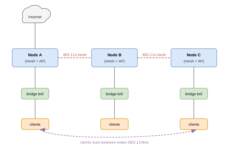
With 802.11r/k/v roaming enabled on the APs (same SSID, same passphrase, same mobility domain), clients hand off between nodes while the mesh carries backhaul traffic.
WDS Backhaul and Repeaters
A WiFi station normally carries only its own traffic and cannot be a bridge port. In 4-address mode, also called WDS, it can forward traffic for the devices behind it. That is what makes a device with a station and an access point a repeater, and a device with a station and wired ports a wireless bridge.
Both ends take part. The satellite enables wds on its station. The
root accepts the station on one of its access points and gives it a
wds-link interface: a bridge port, one per satellite, created by
configuration and tied to the satellite's MAC address.
Compared to an 802.11s mesh, a WDS backhaul is a star with one root, without multi-hop or self-healing. In return it is a plain access point and station link.
Root: access point with WDS ports
On the root, two kinds of interface share the job. The access point is
the one the satellites connect to: it advertises the backhaul SSID and
handles authentication, and there is one per radio. Each wds-link
is the port for one satellite: that is where its traffic appears and
what you put in the bridge. With two satellites on radio1:
radio1
 ├── backhaul    access point, the SSID the satellites connect to
 ├── wds-garage  port for the garage satellite, bridge port
 └── wds-attic   port for the attic satellite, bridge port
A 4-address station forwards traffic for the devices behind it, so it
cannot share the access point's interface with the ordinary clients.
The wds-link is that separate port. Any access point can take WDS
stations, even one that serves clients, but give the backhaul its own
SSID, advertised by the root only, so the satellites can land nowhere
else. For each satellite, add a wds-link interface naming the access
point and the satellite's station MAC address, and make it a port of
the bridge. The interface uses the access point's radio and MAC
address, so it takes neither a radio nor a custom-phys-address.
admin@root:/config/> edit interface backhaul
admin@root:/config/interface/backhaul/> set wifi radio radio1
admin@root:/config/interface/backhaul/> set wifi access-point ssid my-backhaul
admin@root:/config/interface/backhaul/> set wifi access-point security secret backhaul-key
admin@root:/config/interface/backhaul/> end
admin@root:/config/> edit interface wds-garage
admin@root:/config/interface/wds-garage/> set type wifi
admin@root:/config/interface/wds-garage/> set wifi wds-link access-point backhaul
admin@root:/config/interface/wds-garage/> set wifi wds-link peer-address 02:13:37:13:37:12
admin@root:/config/interface/wds-garage/> set bridge-port bridge br0
admin@root:/config/interface/wds-garage/> leave
VLANs and other bridge port settings are configured on the wds-link
interface like on any other port. The port is down until the satellite
connects, and goes down again when it leaves, or within about half a
minute if the satellite disappears without notice:
admin@root:/> show interface wds-garage
name               : wds-garage
type               : wifi
operational status : up
higher-layer-if    : br0
mode               : wds-link
connected          : yes
signal             : -48 dBm (good)
Satellite: 4-address station
On the satellite, configure a station for the backhaul SSID with wds
enabled and make it a bridge port, next to the wired ports and any local
access points. peer-bssid is optional and pins the station to the
root's access point:
admin@garage:/config/> edit interface uplink
admin@garage:/config/interface/uplink/> set wifi radio radio1
admin@garage:/config/interface/uplink/> set wifi station ssid my-backhaul
admin@garage:/config/interface/uplink/> set wifi station wds true
admin@garage:/config/interface/uplink/> set wifi station peer-bssid 02:13:37:13:37:01
admin@garage:/config/interface/uplink/> set wifi station security secret backhaul-key
admin@garage:/config/interface/uplink/> set bridge-port bridge br0
admin@garage:/config/interface/uplink/> leave
A station without wds cannot be a bridge port, the configuration is
rejected.
The access point at the other end must accept 4-address stations. A
root with a wds-link for the satellite does, and so do most access
points with a WDS or 4-address option. One that does not still lets
the station connect and authenticate, then drops all its traffic.
Behind such an access point, use a plain station with an address of its
own and route or masquerade the network behind it instead, see
Firewall.
Repeater
A repeater is a satellite that also runs an access point for clients, bridged with the backhaul station. The station and the access point can share a radio, but then all radios in the backhaul must use the same channel: the station follows the root's channel and the local access point has a fixed one. A channel change on the root, for example from radar detection, leaves the satellites disconnected until they are reconfigured.
Clients on a repeater keep their own MAC addresses, so DHCP reservations and per-port VLANs work as on a wired network. With the same client SSID on the root and the repeaters, the roaming features apply as usual. Keep the backhaul SSID separate from the client SSIDs, or a satellite may connect to another satellite instead of the root.
A satellite with both a WDS backhaul and a cable to the same LAN forms a loop, as with any two bridge ports to the same network.
Troubleshooting
Use show interface wifi0 to verify signal strength and connection status.
If issues arise, try the following troubleshooting steps:
- Verify signal strength: Check that the target network shows "good" or "excellent" signal in scan results
- Check credentials: Use
show keystore symmetric <name>to verify the passphrase matches the network password - Review logs: Check system logs with
show logfor Wi-Fi related errors - Regulatory compliance: Ensure the WiFi country code matches your location
- Hardware detection: Confirm the WiFi radio appears in
show
   hardware
If issues persist, check the system log for specific error messages that can help identify the root cause.