WiFi on the BPI-R4, From Zero to Two Radios
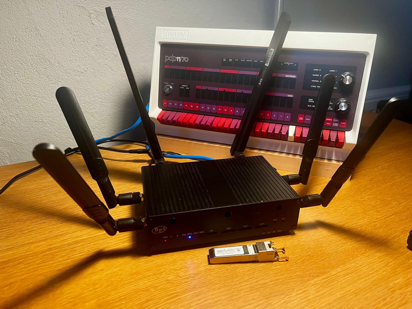
The plan was simple: put a BPI-MT7615 WiFi card and an NVMe disk in a Banana Pi BPI-R4, set up an access point, and verify that a rework of how the hardware configuration is applied had not broken WiFi. It took a bit longer than that.
This post starts with the short version, how to set up an access point in Infix, and then goes through what we found on the way and what we did about it.
An access point in five steps
All of this is done from the CLI, in configure mode. Start with the country code. It decides which channels and transmit power are legal where you are, and until it is set the radio stays in the “world” domain, where no access point can be started:
admin@bpi:/> configure
admin@bpi:/config/> set hardware wifi country-code SE
Then the radio. Radios are found at boot and named radio0,
radio1, and so on. An access point needs a band, and a channel and
channel width to go with it:
admin@bpi:/config/> edit hardware component radio0 wifi-radio
admin@bpi:/config/hardware/component/radio0/wifi-radio/> set band 5GHz
admin@bpi:/config/hardware/component/radio0/wifi-radio/> set channel 36
admin@bpi:/config/hardware/component/radio0/wifi-radio/> set channel-width 80MHz
admin@bpi:/config/hardware/component/radio0/wifi-radio/> end
The WiFi password lives in the keystore, so that it is never shown in clear text in the configuration. The CLI asks for it twice:
admin@bpi:/config/> edit keystore symmetric-key wifi-secret
admin@bpi:/config/keystore/…/wifi-secret/> set key-format passphrase-key-format
admin@bpi:/config/keystore/…/wifi-secret/> edit cleartext-symmetric-key
Passphrase: ************
Retype passphrase: ************
admin@bpi:/config/keystore/…/wifi-secret/> end
Now the access point itself. An interface named wifi0 is a WiFi
interface by default, it only needs a radio, a network name, and the
password. Adding it to the LAN bridge, br0, gives WiFi clients the
same network as the LAN ports:
admin@bpi:/config/> edit interface wifi0
admin@bpi:/config/interface/wifi0/> set wifi radio radio0
admin@bpi:/config/interface/wifi0/> set wifi access-point ssid bpi-test
admin@bpi:/config/interface/wifi0/> set wifi access-point security secret wifi-secret
admin@bpi:/config/interface/wifi0/> set bridge-port bridge br0
admin@bpi:/config/interface/wifi0/> leave
Finally, save it so it survives a reboot:
admin@bpi:/> copy running-config startup-config
show interface wifi0 shows the state of the access point. The WiFi
documentation covers the rest:
station mode, several networks on one radio, roaming, and mesh.
That is how it should go. Here is how it went.
Nothing on the PCIe bus
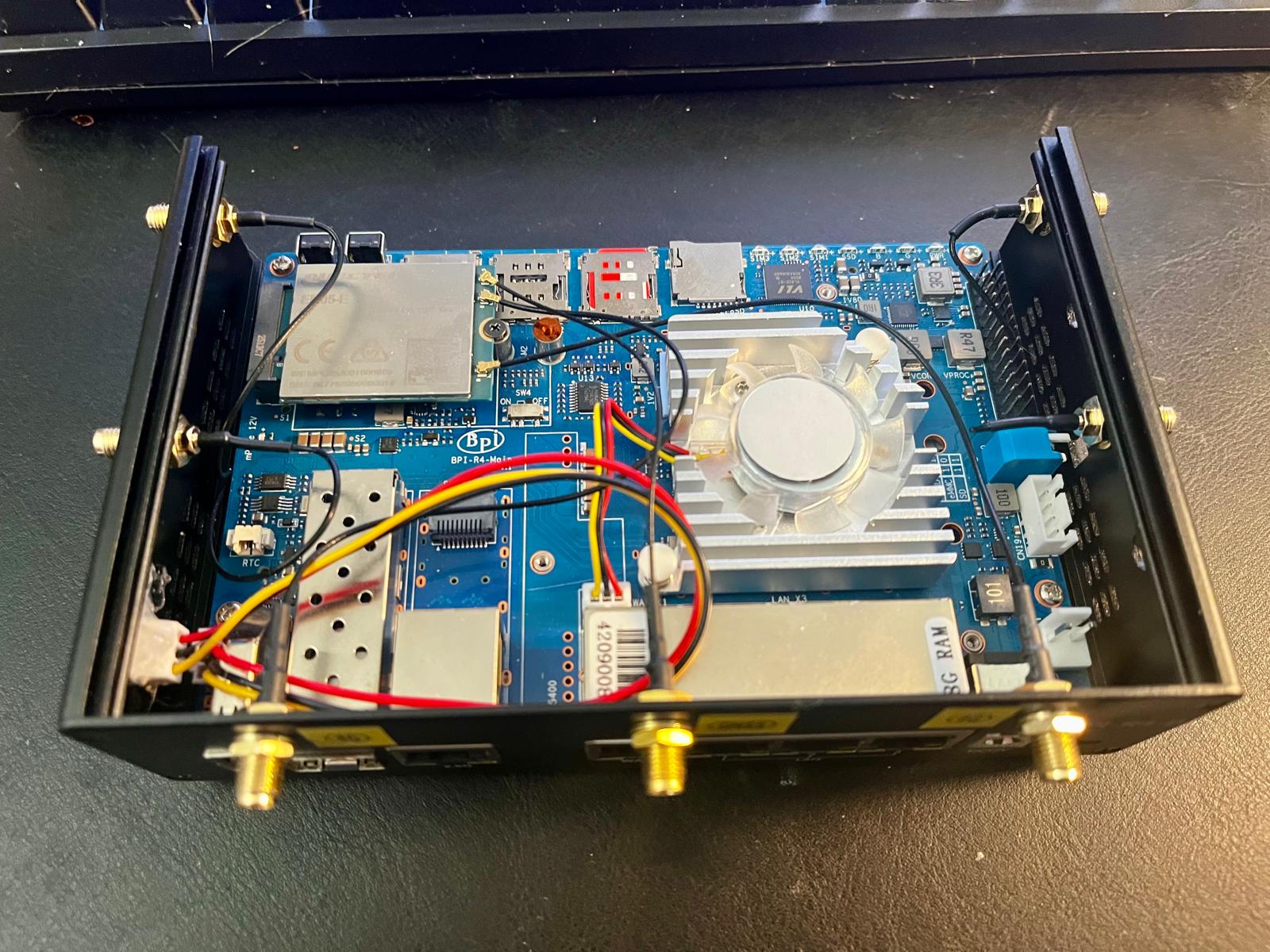 Figure 1: The BPI-R4 with the top off, the Quectel EM05 LTE modem in the M.2 slot at the top left, next to the SIM holders. Photo: J. Wiberg.
Neither card showed up. No WiFi radio, no nvme0, and an empty
/sys/bus/pci/devices/. All four PCIe ports failed the same way:
1
2
mtk-pcie-gen3 11300000.pcie: PCIe link down, current LTSSM state: detect.quiet (0x0)
mtk-pcie-gen3 11300000.pcie: probe with driver mtk-pcie-gen3 failed with error -110
detect.quiet is the very first state of link training, so the
controller never even saw a device. With four slots failing in the
same way, the cards were not to blame. An OpenWrt issue
had the answer: each port is fed by a 26 MHz clock, pextp_p0_sel to
pextp_p3_sel. The boot loader turns them on, but no node in the
device tree references them, so the kernel’s cleanup of unused clocks
turns them off again. On OpenWrt this is a race at boot. Infix
builds the PCIe driver as a module, which loads after the cleanup, so
here it failed on every boot.
The kernel can tell us which clocks are off:
admin@bpi:~$ sudo grep pextp_p /sys/kernel/debug/clk/clk_summary
          pextp_p3_sel     0   0   0   26000000   ...   N   deviceless
          pextp_p2_sel     0   0   0   26000000   ...   N   deviceless
          pextp_p1_sel     0   0   0   26000000   ...   N   deviceless
          pextp_p0_sel     0   0   0   26000000   ...   N   deviceless
The fix in Infix for now is a four line kernel patch that marks these clocks critical, which is what the MediaTek SDK does. The proper fix is to list the clocks in the PCIe nodes of the device tree, so the driver enables a clock only for a port in use. That needs a change to the upstream DT binding, and is tracked in issue #1714.
With the patch, both cards came up:
1
2
3
pci 0001:01:00.0: [14c3:7615] type 00 class 0x000280 PCIe Endpoint
pci 0002:01:00.0: [1987:5013] type 00 class 0x010802 PCIe Endpoint
nvme nvme0: 4/0/0 default/read/poll queues
One radio, random MAC
With the five steps above, the access point came up and a phone
connected. But the MT7615 is sold as dual band, and there was only
one radio, radio0, which can run on either 2.4 or 5 GHz, one band at
a time. The kernel also had something to say about the MAC address:
1
mt7615e 0001:01:00.0: Invalid MAC address, using random address 06:0e:56:91:b5:19
The driver reads the card’s EEPROM to learn its MAC address and its band configuration. Dumping what the driver ended up with tells the story:
admin@bpi:~$ sudo od -A x -t x1 -N 64 /sys/kernel/debug/ieee80211/radio0/mt76/eeprom
000000 00 00 20 00 00 00 00 00 00 00 15 76 c3 14 00 80
000010 02 00 c3 14 15 76 03 22 ff ff 23 04 0d 02 8f 02
000020 00 80 0a 20 00 00 00 00 00 00 00 00 00 00 00 00
000030 20 08 00 00 44 00 00 60 01 01 00 00 00 00 00 00
On a programmed card the first two bytes are the chip ID, 15 76,
followed by the MAC address at offset 0x04. Here both are zero.
The driver rejects the EEPROM and falls back to the chip’s one time
programmable memory, which holds little more than the PCI IDs. Byte
0x3e, where bits 5:4 select the band, is zero too, which means “one
radio, either band”. Only the value 3, DBDC (dual band, dual
concurrent), gives one radio per band.
There are two chips with this PCI ID: the MT7615N with one radio, and the MT7615D with two. The driver cannot tell them apart, only the EEPROM can, and this one says nothing.
Two radios after all
So we asked the driver to try. A new force_dbdc option to the
mt7615_common module treats an EEPROM that selects no band as DBDC:
admin@bpi:~$ echo "options mt7615_common force_dbdc=1" | sudo tee /etc/modprobe.d/mt7615.conf
admin@bpi:~$ sudo rmmod mt7615e mt7615_common
admin@bpi:~$ sudo modprobe mt7615e
The firmware accepted it and a second radio appeared. An MT7615D
after all, with half its radio switched off by an empty EEPROM. With
DBDC the antennas are split between the bands, so radio0 is now
2.4 GHz only and radio1 5 GHz only, two streams each.
An EEPROM image from the aux partition
A module option works, but the MAC address is still random, and it does not help a board where the option is the wrong choice. The better fix is to give the card the EEPROM it was shipped without.
We have done this before. The BPI-R3 has no EEPROM with a MAC address
either, so Infix lets you store a VPD record as
/mnt/aux/vpd.bin. The boot loader copies the file to a reserved
memory region, and the device tree describes that region as an nvmem
provider the kernel can read the board’s identity from.
The mt76 WiFi driver can read its EEPROM from an nvmem cell too. So on
the BPI-R4 the boot loader now also copies /mnt/aux/wifi-eeprom.bin
to reserved memory, and the device tree points the card in mPCIe slot
CN14 at it. Without the file, the region is zeroed, the driver rejects
it, and the card works as before.
This only works with the card in CN14, the mPCIe slot marked SIM3 on the underside of the board. The device tree points only that slot at the EEPROM image, so a card in the other mPCIe slot, SIM2, is left with its empty EEPROM.
To make the image, start from the dump of what the driver uses today,
then set a MAC address and the band configuration with a new
utils/mt7615-eeprom.sh script in the Infix source tree:
admin@bpi:~$ sudo cat /sys/kernel/debug/ieee80211/radio0/mt76/eeprom > wifi-eeprom.bin
$ utils/mt7615-eeprom.sh -b dbdc -m 02:00:00:76:15:00 wifi-eeprom.bin
chip-id : 0x7615
mac     : 02:00:00:76:15:00
band    : dbdc
Copy it back to the board as /mnt/aux/wifi-eeprom.bin and reboot.
The “Invalid MAC address” message is gone, the driver registers two
radios with no module option, and they keep their addresses:
admin@bpi:~$ cat /sys/class/ieee80211/radio0/macaddress
02:00:00:76:15:00
admin@bpi:~$ cat /sys/class/ieee80211/radio1/macaddress
82:00:00:76:15:00
The second radio’s address is derived from the first by the driver. The WiFi interfaces themselves get their addresses from the chassis MAC, like on any other Infix board.
One caveat: the image holds no more calibration data than the card has without it, so range and throughput may be lower than with a factory programmed EEPROM. In our testing both bands worked fine for a phone in the same room.
One access point per band
With two radios, the setup from the start of this post gets a second
access point. The first one moves to 2.4 GHz, where 20 MHz channels
are the polite choice, and wifi1 takes over 5 GHz on radio1. Both
use the same network name and password, so a client can pick the band
that suits it:
admin@bpi:/> configure
admin@bpi:/config/> edit hardware component radio0 wifi-radio
admin@bpi:/config/hardware/component/radio0/wifi-radio/> set band 2.4GHz
admin@bpi:/config/hardware/component/radio0/wifi-radio/> set channel 6
admin@bpi:/config/hardware/component/radio0/wifi-radio/> set channel-width 20MHz
admin@bpi:/config/hardware/component/radio0/wifi-radio/> end
admin@bpi:/config/> edit hardware component radio1 wifi-radio
admin@bpi:/config/hardware/component/radio1/wifi-radio/> set band 5GHz
admin@bpi:/config/hardware/component/radio1/wifi-radio/> set channel 36
admin@bpi:/config/hardware/component/radio1/wifi-radio/> set channel-width 80MHz
admin@bpi:/config/hardware/component/radio1/wifi-radio/> end
admin@bpi:/config/> edit interface wifi1
admin@bpi:/config/interface/wifi1/> set wifi radio radio1
admin@bpi:/config/interface/wifi1/> set wifi access-point ssid bpi-test
admin@bpi:/config/interface/wifi1/> set wifi access-point security secret wifi-secret
admin@bpi:/config/interface/wifi1/> set bridge-port bridge br0
admin@bpi:/config/interface/wifi1/> leave
admin@bpi:/> copy running-config startup-config
While we were at it
The BPI-R4 has no VPD EEPROM either, so every port got a random MAC
address on each boot, and the hostname, derived from the base address,
changed with it. It now gets the same /mnt/aux/vpd.bin support as
the BPI-R3:
admin@bpi:~$ echo '{"mac-address":"02:00:00:ba:42:00","serial-number":"banana4","vendor":"SinoVoip Co., Ltd.","product-name":"BPI-R4"}' \
  | onieprom -e > /tmp/vpd.bin && sudo cp /tmp/vpd.bin /mnt/aux/vpd.bin
After a reboot the board is bpi-ba-42-00, and each port has a fixed
offset from the base address, listed in the board README.
Availability
All of this lands in Infix v26.10: the PCIe clock fix, the
force_dbdc option, the EEPROM script, and the aux partition support
for both files on the BPI-R4. The EEPROM and VPD files need the boot
loader from the same release.